One of the most common example uses stated for a LineString geometry (or geography) in SQL Server is to model a road. In fact, a LineString geometry is ideally suited to almost any transit route – it is a simple, one-dimensional geometry, which is directed (i.e. it has a defined start and end point, which is useful for representing one-way routes), and it can be used with a range of useful methods such as STCrosses(), STLength(), STIntersects().
However, whilst it’s well known that a (single) LineString geometry can represent a (single) road, it is pretty unlikely that you’ll want to ever consider one road in isolation. I haven’t seen many discussions about different approaches to storing a connected network of roads in SQL Server, which is what I hope to briefly introduce in this post.
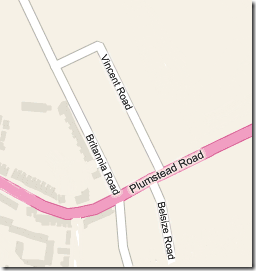
All of the following examples show different ways of modelling a few roads in Norwich, as shown on the following tile from Bing Maps:
Approach #1 Single Table – One LineString per Road.
If your application needs only to consider each road as a separate entity (say, for plotting roads on a map, or for identifying those roads that lie within a certain distance of a point), then network topology can be ignored. Each road can be stored as a separate LineString in a straightforward “Roads” table, as follows:
DECLARE @Roads TABLE (
 RoadId int,
 RoadName varchar(32),
 RoadGeometry geography
);

INSERT INTO @Roads VALUES
(1, 'Britannia Road', 'LINESTRING(1.313772 52.636871,1.316401 52.633518,1.316497 52.632869,1.316642 52.632542)'),
(2, 'Belsize Road', 'LINESTRING(1.317538 52.632697,1.317307 52.633448,1.317098 52.633749)'),
(3, 'Vincent Road', 'LINESTRING(1.31734 52.633818, 1.315982 52.635498,1.315038 52.635229)'),
(4, 'Plumstead Road', 'LINESTRING(1.314546 52.633479,1.31529 52.633298,1.315902 52.633363,1.318332 52.634119)');
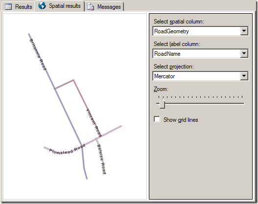
And each row in the table accurately represents the shape of one individual road, shown as follows on the SSMS Spatial Results tab:
SELECT * FROM @Roads;
The problem is that, using this structure, there is no explicit relationship defined between any of the roads – each is treated as a distinct, separate entity, with no connection to each other. In other words, there is no network topology. The only way of defining a logical relationship between any of these roads is based on examining the spatial relationships between the LineStrings representing those roads.
We can see visually that Britannia Road crosses Plumstead Road, and that Vincent Road and Belsize Road are turnings off Plumstead Road. We can also use the inbuilt geometry methods STIntersects(), STTouches(), STCrosses() etc. to test these relationships programmatically. For example, the following code identifies all those roads that intersect Plumstead Road:
DECLARE @g geography;
SET @g = (SELECT RoadGeometry FROM @Roads WHERE RoadName = 'Plumstead Road');

SELECT RoadName FROM @Roads
WHERE RoadGeometry.STIntersects(@g) = 1
AND RoadName <> 'Plumstead Road';
(Note that, by definition, every geometry intersects itself. Therefore we need to add the additional condition to the SELECT statement to avoid including Plumstead Road in the results).
However, there’s a problem with this approach. The results only give two rows: Britannia Road and Belsize Road. Why isn’t Vincent Road being returned? The answer may not be apparent from the Spatial Results tab in SQL Server Management Studio as shown above, but the LineStrings representing Vincent Road and Plumstead Road don’t quite touch. In fact, if you run the following query:
DECLARE @g geometry;
SET @g = (SELECT RoadGeometry FROM @Roads WHERE RoadName = 'Plumstead Road');

DECLARE @h geometry;
SET @h = (SELECT RoadGeometry FROM @Roads WHERE RoadName = 'Vincent Road');

SELECT @g.STDistance(@h);
You’ll see that the result is 7.27813053755075E-06 – in other words there is a gap of 7 micrometres between them. While this is unlikely to matter if all you want to do is display the roads (unless you’re using an insane map zoom level!), it clearly makes a great deal of difference if you’re using intersection to infer connection between these roads. Also note that although there are two turnings from Plumstead Road onto Britannia Road (depending on whether you turn left or right onto Britannia Road), this only counts as one intersection, so it is only returned once in the results.
To model the topological structure of a road network for routing or analysis purposes, we clearly need an alternative model.
Approach #2 Single Table – Multiple Segmented LineString Edges
The next approach might be, rather than describe each road as a single LineString, to split each road up into a number of connected LineString segments. The end point of each LineString segment implicitly defines an intersection at which that road connects with another road, or to the next segment of the current road. This should avoid the problems with the previous model, since any two roads that intersect will both share exactly the same start/end point – there should be no ambiguity caused by one road running close to (but not quite intersecting) another, and there can be an infinite number of LineStrings that share a common start/end point. In fact, this model provides far more flexibility than the previous model, because it is also possible to define roads that intersect but are not connected (that is, they intersect somewhere mid-LineString and not at the start/end point of a segment).
To keep track of which segment(s) are part of which road, we can relate each SegmentId to it’s corresponding RoadId and, as each Segment belongs to one and only one Road, we can add the RoadId directly to the Segments table without affecting normalisation.
The following code demonstrates this approach to define the same example roads as used previously:
DECLARE @Roads TABLE (
 RoadId int,
 RoadName varchar(32)
);

INSERT INTO @Roads VALUES
(1, 'Britannia Road'),
(2, 'Belsize Road'),
(3, 'Vincent Road'),
(4, 'Plumstead Road');

DECLARE @RoadSegments TABLE (
 SegmentId int,
 RoadId int,
 SegmentGeometry geography
);

INSERT INTO @RoadSegments VALUES
(1, 1, 'LINESTRING(1.313772 52.636871, 1.315038 52.635229)'),
(2, 1, 'LINESTRING(1.315038 52.635229,1.316052 52.63399,1.316401 52.633518)'),
(3, 1, 'LINESTRING(1.316401 52.633518,1.316497 52.632869,1.316642 52.632542)'),
(4, 2, 'LINESTRING(1.317538 52.632697,1.317307 52.633448,1.317098 52.633749)'),
(5, 3, 'LINESTRING(1.31734 52.633818,1.315982 52.635498,1.315038 52.635229)'),
(6, 4, 'LINESTRING(1.314546 52.633479,1.31529 52.633298,1.315902 52.633363,1.316401 52.633518)'),
(7, 4, 'LINESTRING(1.316401 52.633518,1.317097 52.633749)'),
(8, 4, 'LINESTRING(1.317098 52.633749,1.31734 52.633818)'),
(9, 4, 'LINESTRING(1.31734 52.633818,1.318332 52.634119)');
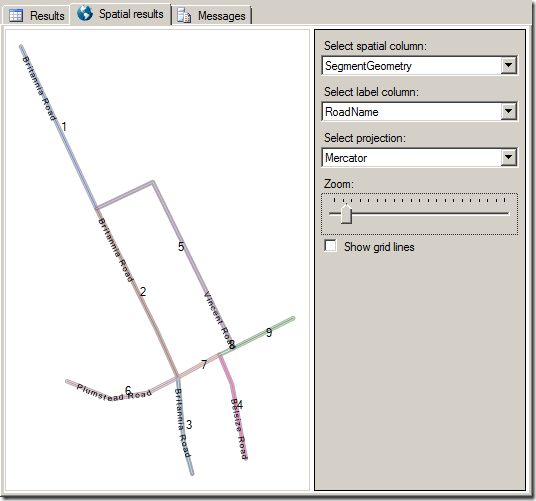
To view the complete road network, we can now run the following query:
SELECT *
FROM @RoadSegments rs JOIN @Roads r ON rs.RoadId = r.RoadId
(Note that, in order to buffer the roads a bit and make both the roads names and segment IDs visible, the actual query used to produce the above image was:
SELECT RoadName, SegmentGeometry
FROM @RoadSegments rs JOIN @Roads r ON rs.RoadId = r.RoadId
UNION ALL
SELECT '    ' + CAST(SegmentID AS varchar(32)) AS RoadName, SegmentGeometry.STBuffer(2) AS SegmentGeometry
FROM @RoadSegments rs JOIN @Roads r ON rs.RoadId = r.RoadId)
We can now find all those roads that are accessible from Plumstead Road using the following query:
DECLARE @RoadID int;
SET @RoadID = (SELECT RoadID FROM @Roads WHERE RoadName = 'Plumstead Road');

SELECT r.RoadName, rs.SegmentGeometry.STAsText()
FROM @RoadSegments rs
JOIN @Roads r ON rs.RoadId = r.RoadId
JOIN (SELECT SegmentGeometry.STEndPoint() AS Node
 FROM @RoadSegments rs
 WHERE rs.RoadID = @RoadID) RoadIntersections
 ON rs.SegmentGeometry.STEndPoint().STEquals(RoadIntersections.Node) = 1
WHERE rs.RoadID <> @RoadID;
The subselect statement in this query first selects the endpoints of each LineString segment that are part of ‘Plumstead Road’. Then, the outer SELECT statement finds all those segments of other roads that start at any of these endpoints.
This approach assumes that all the LineStrings are directed – it only finds those that roads that start at the specified endpoint(s). To find all LineStrings that either start or end at any of the supplied nodes, we can modify the query to become:
DECLARE @RoadID int;
SET @RoadID = (SELECT RoadID FROM @Roads WHERE RoadName = 'Plumstead Road');

SELECT r.RoadName, rs.SegmentGeometry.STAsText()
FROM @RoadSegments rs
JOIN @Roads r ON rs.RoadId = r.RoadId
JOIN (SELECT SegmentGeometry.STStartPoint() AS Node
 FROM @RoadSegments rs
 WHERE rs.RoadID = @RoadID) RoadIntersections
 ON rs.SegmentGeometry.STEndPoint().STEquals(RoadIntersections.Node) = 1
 OR rs.SegmentGeometry.STStartPoint().STEquals(RoadIntersections.Node) = 1
WHERE rs.RoadID <> @RoadID;
This query now assumes all roads are two-way. Note that I’ve included the SegmentGeometry column in the results to demonstrate that the results now include the two different segments of Britannia Road that intersect Plumstead Road:
Britannia Road LINESTRING (1.315038 52.635229, 1.316052 52.63399, 1.316401 52.633518)
Britannia Road LINESTRING (1.316401 52.633518, 1.316497 52.632869, 1.316642 52.632542)
Belsize Road LINESTRING (1.317538 52.632697, 1.317307 52.633448, 1.317098 52.633749)
Vincent Road LINESTRING (1.31734 52.633818, 1.315982 52.635498, 1.315038 52.635229)
Approach #3 Two Tables – Segmented LineString Edges and Intersection Point Nodes
There are still problems with the previous model. From a theoretical point-of-view, it is not necessarily a good idea to tie the spatial relationship between two features to their logical relationship so closely. Just because two roads “touch” doesn’t necessarily mean that one is accessible from the other. Also, it cannot model more complex connections and restrictions between objects that are geographically superimposed but not logically connected (think, for example, of roads that are “no right turn” when approached from a certain direction, but accessible when approached from the other).
Another fundamental problem with the previous approach comes from its practical implementation – since it relies on using the STEquals() method to compare and join the endpoints of road segments together, it is likely to be slow performing when compared to, say a direct join between integer ID fields representing those endpoints in two tables.
Suppose instead, that we added a new table, RoadIntersections, to explicitly define all those points at which two or more roads connected. The RoadIntersections table will contain one row for every road segment that joins a particular intersection. A T-Junction will therefore have three rows inserted into the RoadIntersections table, representing the three road segments that meet at the intersection. The example road network can be modelled using this approach as follows:
DECLARE @Roads TABLE (
 RoadId int,
 RoadName varchar(32)
);

INSERT INTO @Roads VALUES
(1, 'Britannia Road'),
(2, 'Belsize Road'),
(3, 'Vincent Road'),
(4, 'Plumstead Road');

DECLARE @RoadSegments TABLE (
 SegmentId int,
 RoadId int,
 SegmentGeometry geography
);

INSERT INTO @RoadSegments VALUES
(1, 1, 'LINESTRING(1.313772 52.636871, 1.315038 52.635229)'),
(2, 1, 'LINESTRING(1.315038 52.635229,1.316052 52.63399,1.316401 52.633518)'),
(3, 1, 'LINESTRING(1.316401 52.633518,1.316497 52.632869,1.316642 52.632542)'),
(4, 2, 'LINESTRING(1.317538 52.632697,1.317307 52.633448,1.317098 52.633749)'),
(5, 3, 'LINESTRING(1.31734 52.633818,1.315982 52.635498,1.315038 52.635229)'),
(6, 4, 'LINESTRING(1.314546 52.633479,1.31529 52.633298,1.315902 52.633363,1.316401 52.633518)'),
(7, 4, 'LINESTRING(1.316401 52.633518,1.317097 52.633749)'),
(8, 4, 'LINESTRING(1.317098 52.633749,1.31734 52.633818)'),
(9, 4, 'LINESTRING(1.31734 52.633818,1.318332 52.634119)');

DECLARE @RoadIntersections TABLE (
 IntersectionId varchar(32),
 IntersectionLocation geography
);

INSERT INTO @RoadIntersections VALUES
('A', 'POINT(1.315038 52.635229)'),
('B', 'POINT(1.316401 52.633518)'),
('C', 'POINT(1.317097 52.633749)'),
('D', 'POINT(1.31734 52.633818)');

DECLARE @RoadIntersection_Segments TABLE (
 IntersectionId varchar(32),
 SegmentId int
);

INSERT INTO @RoadIntersection_Segments VALUES
('A',1),
('A',2),
('A',5),
('B',2),
('B',6),
('B',3),
('B',7),
('C',7),
('C',4),
('C',8),
('D',5),
('D',8),
('D',9);
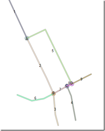
To view all the road segments and intersections in the model, we can now run the following query:
SELECT IntersectionId, IntersectionLocation.STBuffer(7.5) FROM @RoadIntersections
UNION ALL
SELECT CAST(SegmentId AS varchar(32)), segmentgeometry.STBuffer(2)
FROM @RoadSegments rs JOIN @Roads r ON rs.RoadId = r.RoadId
The database structure may seem a lot more complicated than the original single-table approach, but it’s actually more efficient, and a lot more useful. This approach models the road network as a graph (as in graph theory, not as in Excel…), in which each road intersection is a node, and each road segment segment is a distinct edge, connecting exactly two nodes. The spatial relationship between two LineStrings has been separated from their logical relationship – even if two LineStrings touch, the roads represented by those LineStrings are only defined to be topologically connected if they share a common intersection as defined in the RoadIntersections table.
Why does this matter? Well, if your road network conforms to a graph model as above, not only can you perform spatial functions such as STDistance() or STLength() on the LineString geometries that represent individual roads, but you can also apply graph algorithms such as Djikstra or A* to perform routefinding across an entire table of spatial data, traversing across the edges (road segments) of the graph from a chosen start node to another end node, according to the defined network structure. And you can do this right from within SQL Server using a SQLCLR function – but that’s for another post….
As a side-note, you may think that this subject is only relevant if you’re collecting your own spatial data – surely if you’ve imported your road geometry data from an existing source, it will come supplied with the associated links between roads, right? However, this is generally not the case – the most commonly used format for spatial data interchange is the ESRI Shapefile, which represents a single layer of data, containing geometric “features” with certain “attributes”. However, it it does not explicitly define structured relations between those features – these must be created yourself, inferred from the associated attribute data.


