The default Bing Maps road style uses a “hillshade” effect to give an impression of underlying terrain. It’s a relatively subtle, but surprisingly powerful technique to enhance the appearance of map layers, as demonstrated by comparing the following two tiles:

Without hillshading |

With hillshading |
In this post, I’ll describe how to create your own hillshade overlay from digital elevation model (DEM) data, using the GDAL toolset.
By creating the overlay as a set of semi-transparent tiles, rather than pre-rendered into the tiles as shown above, you can place them on top of any Bing Maps/Google Maps et al. tilelayer to represent the underlying terrain.
The process I’ve followed is based on the work of others, most notably PerryGeo, and you can find some other guides on the internet to achieve this same effect. However, I found some of the existing guides on the subject to be either out-of-date or require knowledge of Linux BASH commands etc., so I hope that some of you will find this new step-by-step guide helpful.
1.) Acquire a DEM terrain model
To start with, you’re going to need some source data about the underlying terrain of the earth from which to calculate your hillshade. There’s lots of places to acquire this data from; Perhaps the easiest to use (assuming you’ve got Google Earth installed) is to open the kmz file available from http://www.ambiotek.com/topoview. This uses Google Earth as a graphical interface for v4.1 of the elevation dataset gathered by the Shuttle Radar Topography Mission (SRTM), from which you can click to download individual DEM tiles covering 5°x 5°, as shown below:

Alternatively, you can access these files directly from the KCL server (my former university, incidentally) at http://srtm.geog.kcl.ac.uk/portal/srtm41/srtm_data_geotiff/
The data is provided in GeoTIFF format. You can load one of these tiles up in any graphics program that can load TIFF files, but it won’t look very interesting yet. The height information is encoded in additional metadata that will be ignored by normal graphics programs, so you’ll probably just get an image like this (this is srtm_36_02.tif):

Black parts show the presence of data in the underlying file, which we’ll subsequently process using GDAL tools to create shaded images.
2.) Reproject to Spherical Mercator
Most DEM data sources, including the SRTM data I linked to above, are provided in Plate Carree projection – i.e. WGS84 coordinates of longitude are mapped directly to the x axis of the image, while latitude is mapped directly to the y axis. Before we create tiles from this data suitable for overlay on Bing Maps, Google Maps, et al. we therefore need to transform it into the Spherical Mercator projection. You can do this using gdalwarp, as follows:
gdalwarp -dstnodata 0 -tr 305.7481 305.7481 -multi -co "TILED=YES" -t_srs EPSG:3857 srtm_36_02.tif srtm_36_02_warped.tif |
The full list of parameters accepted by gdalwarp are listed here, but the options I set are as follows:
- dstnodata states what value to use to represent nodata values (the equivalent of null in a SQL database, for example). I’ve set a value of 0 (i.e. black).
- tr gives the target resolution in x and y dimensions. The SRTM data I’m using was recorded at 90m resolution, so you might think that this should be set to 90 90. However, I’m going to be using this data for display on Bing Maps at different zoom levels, which will necessarily involve resampling the image. Therefore, you should set this value to the resolution (in metres/pixel) of the maximum zoom level on which you plan to overlay your data. (Remember that maximum zoom level will have the smallest resolution). You can obtain this value from my Bing Maps Ready Reckoner. In the case above, I’m planning overlaying my data on Zoom Level 9 and above, so I set a value of 305.7481 (in both dimensions). If I’d wanted to go to Zoom Level 10, I would have decreased this to 152.87 instead.
- multi allows parallel processing
- co “TILED=YES” is a format-specific option that states that the output TIFF file should be tiled rather than stripped (see http://www.fileformat.info/format/tiff/egff.htm for an explanation of the difference)
- t_srs gives the destination spatial reference system into which the image should be reprojected. In this case, EPSG:3857, as used by Bing Maps, Google Maps etc.
The resulting image, srtm_36_02_warped.tif, will still be a GeoTIFF file, but will now be projected as follows. The height and width of the output image will depend on the target resolution you specified in the tr parameter:

3.) Convert from DEM to Hillshade
The warped GeoTIFF file has height data encoded in it, but we want to translate that information into a visible shaded effect, and for this we can use gdaldem.
gdaldem actually provides several interesting functions related to working with DEM data, including the ability to derive contour lines, and create shaded relief maps. Maybe I’ll write about these another time, but for this example we want to use the hillshade mode. You can shade the warped image created in the previous step as follows:
gdaldem hillshade srtm_36_02_warped.tif srtm_36_02_warped_hillshade.tif -z 2 -co "TFW=YES" |
This time, I’m only supplying two additional parameters:
- z is a scaling factor applied to the generated hillside image that accentuates the hills, increasing the contrast of the image. I provided a value of 2 just to enhance the effect a bit, but you might decide you don’t need this.
- co “TFW=YES” specifies that the output image should be created with an accompanying “world file”. This is a simple ASCII text file that provides additional information about the geographic extents of the created image, which we’ll need to use in a later step to line the hillshade image up with the Bing Maps tiling system. You can look up more information about world files on wikipedia.
There are additional parameters that allow you to specify the direction and the angle of the light source from which the simulated shadows will be created.
The result of executing the above code will be another TIFF file, in which the background is black, and the elevation data from the DEM has been converted into shades of grey, as follows:

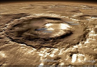
At this stage, you could stop if you wanted to, and simply create a tile layer from the hillshaded image, which would look a bit like this:

Which makes the landscape of North Wales look a bit like the Moon, I think…
To make the data slightly more usable, we need to carry on with a few more tweaks.
4.) Making a Semi-Transparent Overlay
Currently, our hillshade image is opaque, with the shadows cast by terrain represented by variations in brightness of the colour used. To make this into an re-usable overlay that can be used on top of other layers, we need to make the image semitransparent, with shadows cast by terrain being represented by variations in opacity instead.
There are several ways of modifying the image data to achieve this effect. You could do it in Photoshop or another graphics program, for example, or using the graphics libraries in C# or PHP. Since I’m currently trying to learn Python, and GDAL is quite closely linked with Python, I’ll try to do it using the Python Imaging Library instead.
The following Python script makes a number of tweaks to the image above. Firstly, it converts it to a pure greyscale image (while the image above looks greyscale, it’s actually using a colour palette). It then inverts the image, turning it into a negative image. The reason for the inversion is that we then copy the (single) channel of the greyscale image into the opacity channel of a new RGBA image – areas that were very light in the source want to have very low opacity in the transparent image, and vice-versa, so the channel needs to be inverted.
Finally, we scan through the data to find instances of pixels that are pure black (RGBA value 0, 0, 0, 255) –this was the nodata value we set in step one – and replace them with pure transparent pixels (0, 0, 0, 0). The alpha channel in the tuples of any other pixels is also lightened slightly – I chose a value of 74 somewhat arbitrarily because I thought the resulting image looked good – you can choose whatever value you want, or none at all.
[php]
from PIL import Image as PImage
from PIL import ImageOps
# Load the source file
src = PImage.open("srtm_36_02_warped_hillshade.tif")
# Convert to single channel
grey = ImageOps.grayscale(src)
# Make negative image
neg = ImageOps.invert(grey)
# Split channels
bands = neg.split()
# Create a new (black) image
black = PImage.new(‘RGBA’, src.size)
# Copy inverted source into alpha channel of black image
black.putalpha(bands[0])
# Return a pixel access object that can be used to read and modify pixels
pixdata = black.load()
# Loop through image data
for y in xrange(black.size[1]):
for x in xrange(black.size[0]):
# Replace black pixels with pure transparent
if pixdata[x, y] == (0, 0, 0, 255):
pixdata[x, y] = (0, 0, 0, 0)
# Lighten pixels slightly
else:
a = pixdata[x, y]
pixdata[x, y] = a[:-1] + (a[-1]-74,)
# Save as PNG
black.save("srtm_36_02_warped_hillshade_alpha.png", "png")
[/php]
(Much of the logic in this script came from here). The resulting image will be a PNG file, in which darker shadows are represented by increasingly opaque black parts, while lighter shadows are more transparent: